
Since getting my hands on the new Raspberry Pi Model A+, I have been trying to understand how to use use the two hardware PWM pins. I did a quick test using the oscilloscope in my previous post.
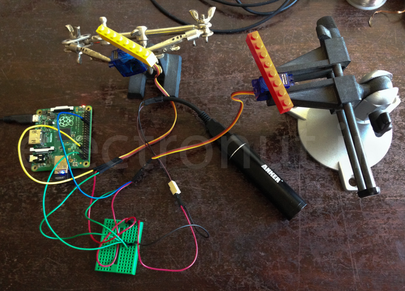
I hooked up two servos to my Pi. The signal lines of the servos are connected to the Pi's hardware pins (GPIO18 and GPIO13), and the servos are powered separately. (My Anker rechargeable 5V battery has battery can barely power these. I'll need to set up a LiPo battery.)
Below is the Python code used to test these. I use wiringPi to set the PWM parameters, but I found the values to be a bit confusing. The base clock has a frequency of 19.2 MHz. Setting a divisor of 400 along with a "range" of 1024 gives us a PWM frequency of 19200000/400/1024 = 46.875 Hz, or a period of 21.3 milli seconds. Generally servos require a pulse of 1 to 2 milliseconds with a 20 millisecond separation. So the above should work, and it does.
And here are the two servos in action!